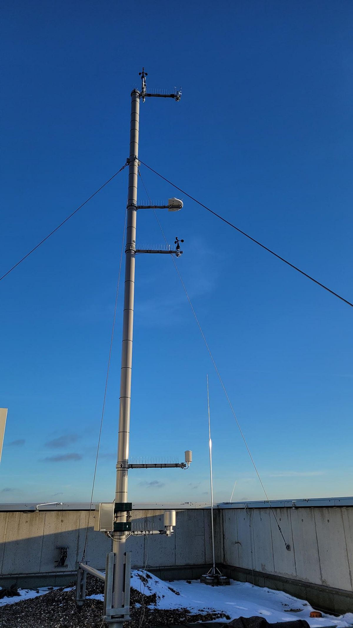
Detailed description of the measuring instruments
Measuring Station "Centre"
Position:
geographical latitude 54°19.4' N
geographical longitude 10°10,5' E
Layout of the measuring station
-measuring station stands on approx. 30m high institude building-
----------------------------------------------------------
10m [Wind measurements]
Anemometer [m/s]
Ultrasonic Anemometer [m/s]
Wind vane [Degree]
-----------------------------------------------------------
7m [shortwave/ longwave radiation]
CMP11 Pyranometer [W/m²]
CGR4 Pyrgeometer [W/m²]
---------------------------------------------------------------
6m [Wind measurements]
Anemometer 2 [m/s]
---------------------------------------------------------------
~2,5m [Temperature& Humidity]
Temperature- [°C]/ Humidity Sensor [%]
---------------------------------------------------------------
~1,5m [Precipitation, Air Pressure]
Rain gauge [mm]
Barometer [hPa]
Anemometer
Wind speed [m/s]
Technical specification:
- Measuring range: 0,3 - 60 [m/s]
- Accuracy: +/- 0,3 [m/s]
- integrated 15W heating system
- Data output: 4-20 mA
- METEK GmbH
How it works:
- The anemometer consists of a three-armed (sometimes four-armed) star with hemispherical hollow shells. When the wind blows into these freely rotating shells, they are set in motion.
- The wind speed is then derived from the rotational movement (rotations per minute).
2D-ultrasonic Anemometer
Wind speed [m/s]
Technical specification:
- Wind speed: 0 – 75 m/s
- Wind direction: 0 – 359°
- Heating system in Transducer
- Works according to the Transit-Time Difference method
- Analog output: 4...20 mA
- WSWD sonic anemometer, MESA Systemtechnik GmbH
How it works:
- Determines the horizontal components wind speed and wind direction of the three-dimensional wind vector (parallel flow to the earth's surface).
- The right-angled velocity components are calculated from two orthogonal measurement sections.
- The polar coordinates can in turn be calculated from the two X and Y wind components as the magnitude and angle of the wind speed.
Physical background:
- Sound is a deformation that propagates as a wave in a medium and travels at different speeds in different media (propagation speed of sound in still air ~343 m/s)
- If the medium air is moved, the speed component of the air movement is superimposed on the speed of propagation in still air.
- This means that a wind speed component in the propagation direction of the sound accelerates the sound and an opposite wind speed component reduces the propagation speed of the sound.
- The wind speed component of the respective measuring section can be determined from the difference in the transit times of the two superimposed propagation speeds.
- The high temperature influence on the measurement result can be eliminated as the transit times per measurement path are measured in both directions Transit times can be determined more precisely with high frequencies, so that high frequencies are used over short distances --> Ultrasonic
Wind vane
Wind direction [degree]
Technical specification:
- Measuring range: 360°
- max. strength capacity: 100 m/s
- heavy duty version
- Metek GmbH
How it works:
- The wind vane always aligns itself parallel to the local wind direction due to the wind pressure, the position of which (0 - 359 degrees) is then scanned electronically.
Pyranometer
Shortwave radiation [W/m²]
Technical specification:
- Sensitivity: 7...14 μV/W/m²
- Spectral range (50% Punkte): 300...2800 nm
- Operating temperature: -40 ... +80 °C
- Max. radiation: 4000 W/m²
- Tilt error (at 1000 W/m²): < 0,2 %
- Directional error (at 80 ° with 1000 W/m² beam): < 10 W/m²
- Zero offsets: Thermal radiation (200 W/M²) : < 7 W/m² % Temperature change ( 5 K/hr) : < 2 W/m²
- Version: CMP 11 by Kipp & Zonen
How it works:
- The hemispherical glass dome acts like an edge filter and therefore only lets through the incoming shortwave solar radiation, which then heats a black metal plate underneath.
- A blackened thermopile underneath, consisting of thermocouples connected in series, now serves as the measuring sensor.
- The temperature differences that occur generate thermoelectric voltages, which are a measure of the radiation intensity received.
Additional information:
- Thermopile: a series connection of thermocouples as radiation receivers in which the cooler solder joints are kept at a constant temperature while the warmer ends are exposed to radiation. The heating of these solder joints generates an electrical voltage from which the radiation intensity can be derived.
- The temperature rise is slightly influenced by wind, air and radiation loss to the environment. For this reason, the detector is protected by a glass dome.
Pyrgeometer
Longwave radiation [W/m²]
Technical specification:
- Sensitivity: 5 bis 15 µV/W/m²
- Operating temperature: -40 to +80 °C
- Field of view: 180°
- Range of irradiance: -250 to + 250 W/m²
- Spectral range: 4,5 bis 42 μm (50% Punkte)
- Dome heating offset: <4 W/m²
- CGR 4 Pyrgeometer by Kipp & Zonen
How it works:
- A pyrgeometer consists of an edge filter (here the glass dome), which keeps out the solar part of the radiation, and a black surface, which absorbs the transmitted radiation and thus heats it.
- The upward-facing black metal surface is thus electrically heated until it has the same temperature as a downward-facing bare metal surface.
- The pyrgeometer therefore supplies a voltage that is proportional to the radiation exchange between the instrument and the sky/ground in its field of view.
- The output signal of the detector can therefore be positive or negative.
Example: The sky is colder than the pyrgeometer --> the instrument radiates energy to the sky, the output signal is then negative.
Additional information:
- All pyrgeometers use infrared glass materials that absorb a large proportion of the short-wave radiation.
- However, the glass heats up and thus produces an offset in the measured values.
- To increase accuracy, it is therefore normally necessary to shade the pyrgeometer from direct sunlight in order to minimize this effect.
- Interesting: In the model of the CGR 4 pyrgeometer used here, this offset is reduced to a negligible level, eliminating the need for temperature measurements or dome shading.
- To avoid the influence of the wind here too, the surfaces are located under a glass dome.
Temperature- & Humidity sensor
Air Temperature [°C], relative Humidity [%]
Technical specification - Temperature sensor:
- Sensor: Platinum resistance Pt100 Temperature sensor
- Measuring range: -40...+60 °C
- Accuracy: +/- 0,2 K (at 23°C)
- Output: measuring resistor Pt 100
- Inside radiation protection cover
- METEK GmbH
How it works:
- Pt temperature sensors are sensors that react to the influence of temperature with a change in resistance.
- The measuring effect is achieved by the dependence of the electrical resistance on the temperature of platinum.
Additional information:
- Platin-measuring resistors are classified according to their material and their nominal resistance rating at a temperature of 0 °C. Pt100 (nominal resistance 100 Ω) is very common, as shown here mounted on the measuring mast. However, higher nominal resistances are also in use.
Technical specification - Humidity sensor:
- Sensor: Kapazitives Messelement
- Measuring range: 0...100 % rF
- Accuracy: 10...90% rF at 23°C --> 1,5%
<10% & >90% rF --> 2%
- Operating temperature: -40...+75 °C
- Min. air velocity at sensor head: 0,5 m/s
- Inside radiation protection cover
- METEK GmbH
How it works:
- Capacitive humidity sensors are based on two electrodes with a non-conductive, moisture-sensitive polymer film between the electrodes to generate an electric field.
- This hygroscopic polymer film absorbs water vapor from the air, resulting in a change in the dielectric constant between the two electrodes, which is then measured by the sensor.
Additional information:
- The general function is therefore based on the changes in the dielectric constant of a material in response to changes in humidity.
- Dielectric constant (permittivity): measures the ability of a material to store electrical energy in an electric field.
Rain gauge
Precipitation [mm]
Technical specification:
- Weighing rain gauge with automatic drain
- Resolution: 0,1 mm
- Accuracy: +/- 2% with intensity compensation
- Opperational range: -20 - +70°C
- Impulse output: Reed contact reverse polarity protected
- Two heating circuits included (winter edition)
- Volume of bucket: 2cm³(2g Wasser), collection area of 200 cm² (WMO-Standard) - one filling corresponds to precipitation height of 0,1mm/m²
- Measuring range: 0 – 8mm/min
How it works:
- Operates with low-friction weighing rocker (tipping bucket) according to Joss Tognini.
- Through the self-emptying tipping-bucket mechanism, a reed contact is closed and the triggered pulse can be electronically scanned and registered.
Additional information:
- The specific Joss-Tognini shape limits the risk of partial emptying and measurement errors.
- With other rain gauge systems, errors occur due to incomplete dripping as a result of surface tension of the precipitation.
- Weighing gauges show more accuracy in regions with mixed or solid precipitation, can measure events as low as 0.025 to 0.05 mm and show more sensitivity than other tipping bucket gauges.
Barometer
Air Pressure [hPa]
Technical specification:
- With piezoresistive sensor element
- Measuring range: 800-1060 hPa
- Accuracy: +/- 0,25 hPa with sensor heating
- Output: 4- 20mA at 800– 1060hPa
- METEK GmbH
How it works:
- Piezoresistive pressure sensors detect the pressure in a room or medium using strain gauges or semiconductor chips.
- Deformation of these elements leads to a change in electrical resistance. This change can then be analyzed to determine the pressure.
- The sensor measures the absolute air pressure or calculates the reduced air pressure using the international altitude formula (DIN ISO 2533).
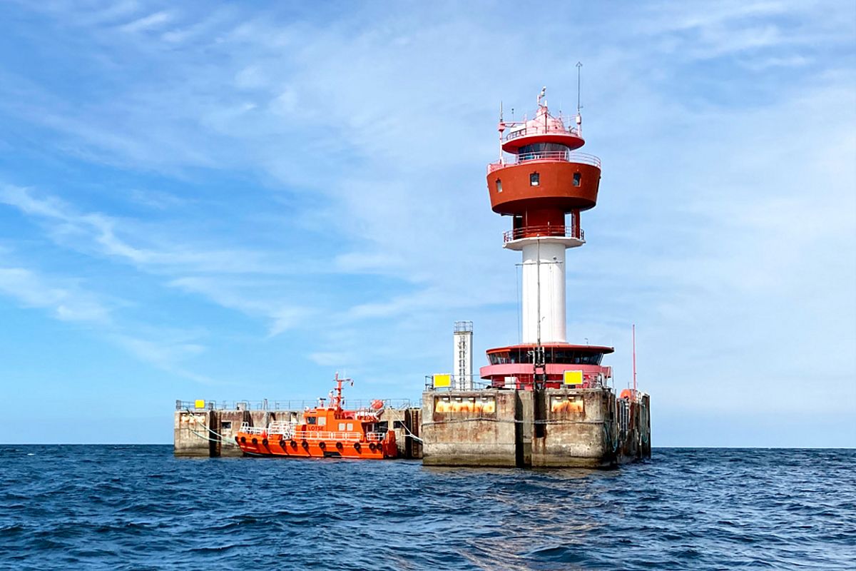
Measuring station "Lighthouse Kieler Bight"
Description of the parameters and measuring devices
Position:
geographical latitude: 54°30' N
geographical longitude: 10°16.5' E
Since May 1, 2015, our own meteorological measurements have been replaced by the measurements of the German Weather Service. The measured values for wind direction, wind speed, maximum wind gust, air temperature, relative humidity and water temperature have been adopted. As before, the data published here are 8-minute averages based on the 1-minute measured values from the German Weather Service. The wind direction is averaged vectorially, but not weighted with the wind speed. The specified maximum wind gust also refers to the 8-minute interval.


![[Translate to English:] Messinstrumente 10m Measuring instruments at 10m height](/fileadmin/_processed_/5/8/csm_20240111_145538_c56a23db46.jpg)

![[Translate to English:] Messinstrumente unterer Teil](/fileadmin/_processed_/a/e/csm_Mast_unten_cd477fdd86.jpg)


